Modern Mulligan
MULLIGAN BLOCKING and its use in constructing billets used in the fabrication of Foamglas® insulation into half sectional pipecover. This method of constructing billets in the shape of trapezoids is believed to have originated in the late 1950’s, and developed by Egmont Smith, President of Pamrod Products Company. Pamrod was the first Foamglas Fabricator located west of the Mississippi River. The Mulligan Manufacturing Company was formed in 1995 as a subsidiary of Pamrod Products Company. Its sole offering was a three wheel tilting band saw, and an instruction manual describing the process of cutting and assembling Foamglas Billets that are trapezoidal in shape. This system was adapted by many of Pittsburgh Corning’s Fabricating distributors as a means to significantly reduce the waste in converting rectangular blocks into pipecovering.
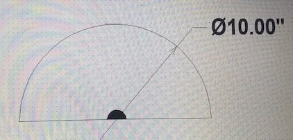
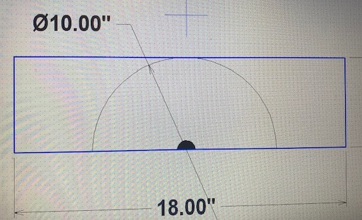
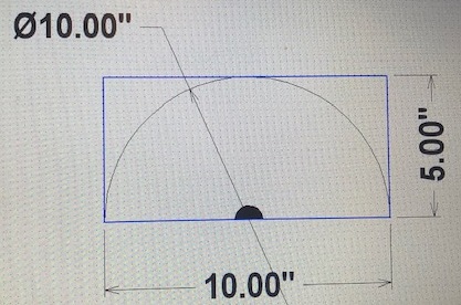
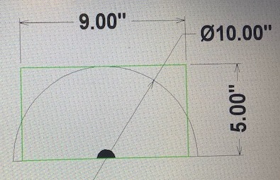
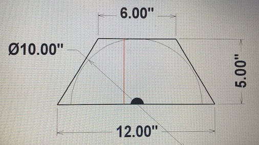
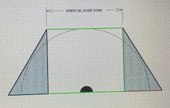
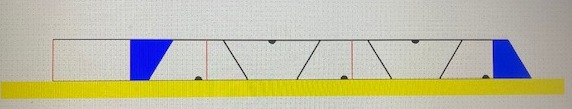
Figure 7
THE MULLIGAN METHOD
The process described above would not lend itself to any type of manufacturing process, simply cutting a block to 9” wide and then splitting it at some angle does not appear to be very efficient – Foamglas® only comes in 18” widths and thicknesses from 2” – 7” in ½” increments. If Foamglas® came in long sheets then you could cut a series of trapezoids inverted to each other resulting in no loss or drops between the billets. This process was accomplished by those fabricators using the Mulligan System and the three wheel tilting band saw by simply cutting one angle, turning the block around to cut a trapezoid, then taking the residual piece, turning it around and flipping it over, adding another block of raw material cutting/making another trapezoid. The issues of glue joints shown in red landing in the hatched area shown in figure 7 was a problem as was determining the best cutting pattern.
The use of a CNC wire cutter or Profiler is the perfect solution to cutting the nested trapezoids shown above in Figure 8. In this example of the 10” OD we determined (did the math) the optimal shape of the trapezoid is 6” on top and 12’ on the bottom using a 5” thick block of raw material. This is also a coincidental event in that one billet requires exactly 9” of material which patterns perfectly out of material that comes in 18” widths. This particular pattern uses 45” of material or 2.5 blocks of material. It could also have been twice as long.
To start the process – three each 18” x 5” blocks are positioned on a profile machine which also has a sacrificial slab (shown in yellow) of material underneath to permit the wire to cut completely through the Foamglas® block. The wire is positioned on top of the blocks at the intersection of the first and second block. The Profile, supplied by LP2 Solutions, is run and proceeds to travel to the left and cut the first block in half (creating a 9” wide starter block – shown in blue) – the wire proceeds to cut the entire profile as shown. The red lines represent the seams when the blocks are laminated into billets – note they all fall within the vertical joint zone. The fifth billet is made from the blue starter block being laminated to the end of the third block.
Two Foamglas blocks can be positioned across the width of the profile machine resulting in twice the production – or in this case 10 LF of billets/run – 100 LF /hour is not unrealistic using this method.
LP2 SOLUTIONS
We invite you to request a sample profile for use in your facility. Simply tell us what diameter billet you want to try, and what combination of blocks required to build it.
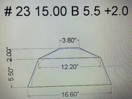
We will email you at no charge or obligation this profile – along with the complete chapter from our Mulligan Book of billets on that billet of your choice. As an example a 15” OD to make 10 x 1 ½” or 8 x 2 1/2” could be made from either our # 23 billet 5.5” + 2.0” or # 25 billets 4.5” + 3.0 (bottom and top block thicknesses).
There are over 100 possible different billet designs for ODs ranging from 10.75 – 28” you won’t need them all but we have them – just in case. A complete library for your shop might consist of one dozen single stage and three dozen two stage. These are available one profile at a time or the complete library whatever your needs and budget permit.
I urge you to compare your current method to the Modern Mulligan – send us a representative drawing/sketch of your current method and we’ll do the analysis for you. Each profile is likely to pay for itself in its first use, that’s what savings of 10, 20 % or more will do for your bottom line.
EMPOWER YOUR PROFILER WITH THE MODERN MULLIGAN METHOD LP2 Solutions has done all the work for you.
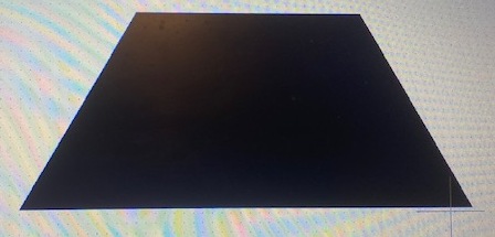
Single stage – six sided
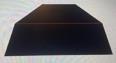
two stages – ten sided
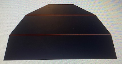
three stages – fourteen sided
The concept has not changed in over 50 years. We believe this method results in half sectional pipecovering with the fewest number of lamination joints possible and consistent with economical use of the raw material. The single stage Mulligan Billet can be used up to and including 14” OD. However, prior to the advent of thicker Foamglas® blocks (greater than 5”) the single stage Mulligan was only possible up to and including 9 5/8” OD billets. These single stage Mulligan Billets have waste factors around 15% as seen in this example and a theoretical minimum of 9.5%.
The two stage Mulligan Billet is recommended up to its maximum size of 28” OD – or using two 7” thick trapezoids – real world waste factors using this method is always less than 10% including many in the 7 %. The three stage Mulligan Billet is for those times you need to provide large sizes half sectional pipecover, typically to fabricate fittings where Quads and Segments won’t work.
There are over 100 different Two Stage Mulligan Billets for OD’s ranging from 10.75 – 28” O. Mulligan billets can be single stage, two stages with two different trapezoids, and three stages.